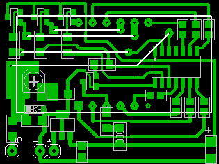
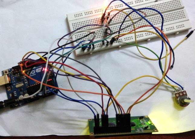
Showing posts with label Dijital Voltmetre. Show all posts

Saturday, 14 March 2020

Arduino and LCD- 0 Volt -- 1000 Volt

Abstract
The Arduino inbuilt 10 bit ADC, can be used for constructing / measuring the 0 Volt to 1000 Volt user selectable Digital Volt Meter. The 16x2 LCD display driver, connected with Arduino Uno will be used for displaying the measured voltage. This voltmeter can read only DC voltage.
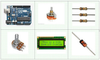
ARDUINO 50V DIGITAL VOLTMETER USING MAX7219

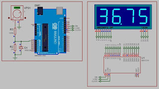
M.Pugazhendi build a digital voltmeter using Arduino and MAX7219 display driver.

The Arduino inbuilt 10 bit ADC, can be used for constructing / measuring the 0Volt to 50Volt Digital Volt Meter. Popular MAX7219 display driver, connected with Arduino Uno will be used for displaying the measured voltage. This voltmeter can read only DC voltage.

Wednesday, 11 March 2020

220 volt şebeke dijital voltmetre yapımı


İşaret, R2 ve R3 dirençlerini bir 4.7k düzeltici ve bir Zener diyot VD1'in olmamasıyla devreden farklıdır.

Şebeke voltmetresinin modifiye edilmiş bir devresi de gönderildi, voltmetrenin voltajını stabilize etmek için daha iyi bir devre ile ayırt edildi.

PIC16F676 mikrodenetleyici kullanarak voltmetre yapımı


PIC16F676 mikrodenetleyicisindeki bir voltmetreye ayrılmış bir makale uzun süre sitede yayınlanmıştır . Zamanla, bazı ziyaretçiler voltmetrede değişiklik yaptı ve bu değişiklikleri paylaşmaya karar verdi. Bunun için minnettarlar.

Makale, PIC16F676 üzerinde yapılan 50 voltluk bir ölçüm limiti olan bir voltmetreyi veya bu mikrodenetleyicinin ADC'sinin nasıl kullanılacağını açıklar.

Monday, 9 March 2020

pic16f676 mikrodenetleyici üzerine voltmetre yapımı

Makale, PIC16F676 üzerinde yapılan 50 voltluk bir ölçüm limiti olan bir voltmetreyi veya bu mikrodenetleyicinin ADC'sinin nasıl kullanılacağını açıklar.

Sunday, 8 March 2020

Digital Voltmeter 0-24V 10Bit 7-Segment

This is an upgrade to recently published Simple Digital Voltmeter.Few improvements were done to hardware and software.DVM operating range  was slightly increased up to 24 V Max, however the most significant change is that the code now uses full 10 bit of ADC resolution to calculate the voltage being measured allowing 3 Digit result  for 0-9.99 range  and 4 digits for 10.00-24.00 range.  Also  generic  Common Cathode 7-Segments were used as they are widely available and can be purchased on Ebay for example. Operational amplifier LM358 and simple RC low pass filter were added to PIC analog input AN1 (Channel 1) to improve circuit stability. Only a simple calibration is needed. Connect 5V to the input, calibrate R1 to display 5.00 V. See attached picture comparing  measurement to Fluke 87 V. Prototype has good accuracy if calibrated correctly.


Thursday, 5 March 2020

Arduino based Digital Ammeter


Ammeter is used to measure current flow through any load or device. Here in this Arduino Ammeter, we will explain about measuring of current by using ohm’s law. It will be quite interesting as well as a good application of basic science that we studied in our school days.

All of us are well known of ohm’s law, It states that “the potential difference between two poles or terminals of an conductor is directly proportional  to the amount of current pass
through the same conductor” for constant of proportionality we use resistance, so here it comes the equation of ohm’s law.

V = IR

V = voltage across the conductor in Volt (v).
I = current pass through the conductor in Ampere (A).
R = resistance constant of proportionality in Ohm (Ω).
In order to find the current pass through the device we just rearrange the equation as below, or we can calculate with ohm's law calculator.

I = V / R

So in order to find out the current, we need some data:

Voltage
Resistance
We are going to build a series resistance along with the device. As we need to find voltage drop across the device, for that we need voltage readings before and after the voltage drop, that is possible in the resistance because of no polarity.

Required Components:

Arduino Uno.
Resistor 22Ω.
LCD 16x2.
LED.
10K pot.
Breadboard.
Multimeter.
Jumper cables.


Circuit Diagram and Connections:
The schematic diagram of the Arduino Ammeter Project is follows


The schematic diagram shows the connection of the Arduino Uno with LCD, resistor and LED. Arduino Uno is the power source of the all other components.

The Arduino has analog and digital pins. The sensor circuit is connected to the analog inputs from which we get value of the voltage. The LCD is connect with the digital pins (7,8,9,10,11,12).

The LCD has 16 pins the first two pins (VSS,VDD) and last two pins(Anode, Cathode) are connected to the gnd and 5v. The reset (RS) and enable (E) pins are connected to the Arduino digital pins 7 and 8. The data pins D4-D7 are connected to the digital pins of Arduino (9,10,11,12). The V0 pin is connected to the middle pin of pot. The red and black wires are 5v and gnd.


Arduino Code:
Complete code for arduino based ammeter to measure current, is given at the end of this article.


#include
LiquidCrystal lcd (7,8,9,10,11,12);

void setup() {
// put your setup code here, to run once:
Serial.begin(9600);
lcd.begin(16,2);
lcd.clear();
}

void loop() {
// put your main code here, to run repeatedly:
int voltage_value0 = analogRead(A0);
int voltage_value1 = analogRead(A1);

 int subraction_value =(voltage_value0 - voltage_value1) ;
 float temp_val = (subraction_value*0.00488);

 float current_value = (temp_val/22);
 Serial.print(current_value);
 lcd.setCursor(0,0);
 lcd.print("current value=");
 lcd.setCursor(0,1);
 lcd.print (current_value);
 lcd.print("A");
 delay(1000);
}


Wednesday, 4 March 2020

Arduino kontrollü laboratuvar güç kaynağı

Bir Arduino bir laboratuvar güç kaynağını kontrol eder. Giriş, bir matris klavyesi veya bir bilgisayardan rahatlıkla yapılır. Hedef ve gerçek değerler ekranda görüntülenir.

malzemeler


Klavye ve matris ekran üzerinden rahat kullanım.

Arduino
4 × 20 LC ekran
Matris klavye
güç Kaynağı
röle
İlham kaynakları

Kötü bir ucuz güç kaynağı ve ne yazık ki kusurlu, kendi kendine yapılan bir güç kaynağı.

Saturday, 6 July 2019

pic ile voltmetre-ampermetre devresi

Sitemizde bulunan 30 volt 5 amper ayarlı güç kaynağı ile kullanabileceğiniz, hem gerilimi 
hem de akımı aynı anda ölçebileceğiniz bir devre tasarladım. Devrede mikrodenetleyici 
olarak pic 18f26k22 kullandım. Bunu tercih etmemin sebebi 28 pinli olması üzerinde 
19 adet adc kanalı bulundurmasıdır.
Devrenin şeması:


Devrede 3 digitlik 2 adet 7 segment kullanıldı.Sol taraf gerilim değerini sağ taraf ise akım 
değerini göstermektedir. 7 segmentlerin bağlantılarının karmaşık olmasının sebebi tamamen
 baskı devrenin çizimini kolaylaştırmak amacıyladır. Başka özel bir sebebi yoktur.

kullanılan malzemeler:

1 adet pic18f26k22
1 adet 28 pin soket
2 adet 3 digit 7 segment anot display
2 adet 10k trimmpot
8 adet 330 ohm direnç
4 adet 10k direnç
2 adet 56k direnç
1 adet  0.47 ohm 5W taş direnç
1 adet 180 ohm 5W taş direnç
1 adet 100 uF 50 V kondansatör
1 adet 1 uF 16 V kondansatör
1 adet lm7805 voltaj regülatörü
3 adet 2'li klemens(isteğe bağlı)

Devrenin çalışma prensibi:

Öncelikle, devremiz 0-40 V arasında ölçüm yapmaktadır. 56k ve 10k lık dirençler bu durum
 öz önüne alınarak seçilmiştir. ''Elimde 56k yok 68k koyayım, 47k koyayım çok bişey farketmez''
 gibisinden düşüncelere kapılmayın çünkü ölçümde çok büyük farklar meydana gelir :) sonra vay 
efendim kapasitör niye patladı :)

Direnç değerleri 40 volt gerilimde adc üzerine 5 volt düşecek şekilde seçilmiştir. Diğer tüm değerler
bu değer referans alınarak hesaplanır. Devredeki trimmpotların amacı, direnç değerlerinde meydana 
gelen hataların devreye yapacağı etkileri ortadan kaldırmaktır. Gerilim ölçümü bu şekilde yapılmaktadır.

Akım ölçümündeki temel prensip, çıkışa seri bağlanan 0.47 ohmluk direncin üzerine düşen gerilimin
 ölçülüp bu direnç değerine bölünmesidir. Bunun için direncin diğer ucundaki gerilim de yukarıda 
anlatılan yöntem ile ölçülüp bu iki gerilim değeri birbirinden çıkartılır ve çıkan sonuç 0.47 ye bölünür.
 direncin bu kadar küçük seçilmesinin sebebi, çıkışa bağlanan devreye olacak etkilerini en aza 
indirebilmektir. Ancak bunun bir de dezavantajları var. örneğin çıkışa bağladığımız devre 2 amper akım 
çeksin. Bu durumda direncin üzerine düşen gerilim=0.47 x 2=0.94 V olacaktır. yani 1 Volt bile değil. 
Bu yüzden ölçümünüzün çok hassas olması gerekmektedir. Eğer kendiniz bu devreyi tekrar tasarlamak istiyorsanız bu konuda dikkatli olmanızı tavsiye ederim.


Devreyi 5x10 luk plakete sığdırmaya çalıştırdığımdan, ne yazık ki devrede 2 adet atlama mevcut. 
atlamaları kırmızı çizgilerle gösterdim. Ancak yakın zamanda devrenin 10x10 luk bir versiyonunu 
da yapacağım, onda hem yollar biraz daha aralıklı olacak hem de atlama olmayacak. Bunu kendi 
güç kaynağıma sığdırabilmek için böyle yaptım siz tercihinize göre istediğinizi kullabilirsiniz.
 muhtemelen 
kod ve şemaları aynı olacak.

Kullanım talimatları :

Devrenin montajı bittikten sonra sol üst köşede güç kaynağı çıkışı yazan yerlere kendi kaynağınızın 
çıkışlarını bağlayınız, toprağa gidecek pinler, altında - işaretiyle çizimde belirtilmiştir. En sağda besleme
 yazan yere, güç kaynağınızda diyot köprüsünün çıkışında bulunan kapasitörün üzerinden aldığınız
 çıkışı bağlayınız. çıkış yazan yere de güç problarını bağlayabilirsiniz. artık yeni çıkışınız burasıdır.

Devreye güç verdikten sonra öncelikle güç kaynağı çıkışı yazan yerdeki gerilimi bir multimetre 
yardımıyla ölçünüz. gerilimi 5 volta getiriniz. multimetrede okunan değer ile devrenin voltmetre
 göstergesi üzerindeki gerilim birbirine eşitlenene kadar en soldaki trimmpot ile ayar yapınız.
 Bunu yaparken devreye hiçbir yük bağlanmamış olmalıdır. Bunu yaptıktan sonra devredeki butona
 bir kez basınız. şu anda devrenizin normalde akımı göstermesi gereken kısmı, çıkışa seri bağlı olan
 direncin çıkış ucundaki gerilimi göstermektedir. Açık devre prensibinden ötürü bu direncin iki ucunda
 da aynı gerilim olması gerekmektedir. Bu durumda soldaki göstergedeki değer ile sağdaki göstergedeki
 değer birbirine eşitlenene kadar sağ tarafta bulunan trimmpot ile ayar yapınız. Bunu yaptıktan sonra 
tekrar butona basınız. Sağdaki gösterge tekrar akım değerini göstermeye başlayacak. bunu da 
yaptıktan sonra devreniz kullanıma hazır. hayırlı olsun :)

DEVREYE AİT DOSYALAR

baskı devre çizimi voltmetrePCB.pdf dosyasındadır.

devrenin çalışma videosu

not; alıntıdır....

Wednesday, 3 July 2019

ARDUINO ENERGY METER - V2.0 & ARDUINO VOLTMETRE - V2.0

Picture of Final TestingHello friend, welcome back after a long break. Earlier I have posted an Instructables on
Arduino Energy Meter which was mainly designed to monitor the power from the solar
panel (DC Power) in my village. It became very popular on the internet, lots of people
all over the world have built their own. So many students have made it for their college
 project by taking help from me. Still, now I am receiving emails and messages from
people with questions regarding hardware and software modification for monitoring
 AC Power consumption.


Saturday, 29 June 2019

Arduino Based Digital Ammeter

Arduino Based Digital Ammeter


Ammeter is used to measure current flow through any load or device. Here in this Arduino Ammeter,
 we will explain about measuring of current by using ohm’s law. It will be quite interesting as 
well as a good application of basic science that we studied in our school days

All of us are well known of ohm’s law, It states that “the potential difference between two poles 
or terminals of an conductor is directly proportional  to the amount of current pass through the 
same conductor” for constant of proportionality we use resistance, so here it comes the equation 
of ohm’s law.
V = IR
  • V = voltage across the conductor in Volt (v).
  • I = current pass through the conductor in Ampere (A).
  • R = resistance constant of proportionality in Ohm (Ω).
In order to find the current pass through the device we just rearrange the equation as
below, or we can calculate with ohm's law calculator.
I = V / R

So in order to find out the current, we need some data:
  1. Voltage
  2. Resistance
We are going to build a series resistance along with the device. As we need to find voltage
drop across the device, for that we need voltage readings before and after the voltage drop,
that is possible in the resistance because of no polarity.


Like in the above diagram, we have to find the two voltages that are flowing across the resistor. 

The difference between the voltages (V1-V2) at the two ends of resistors gives us voltage 
drop across the resistor (R) and we divide the voltage drop by the resistor value we get the 
current flow (I) through the device. That is how we can calculate the Current value passing
 through it, let’s gets into it practical implementation.


Required Components:


  • Arduino Uno.
  • Resistor 22Ω.
  • LCD 16x2.
  • LED.
  • 10K pot.
  • Breadboard.
  • Multimeter.
  • Jumper cables.

Circuit Diagram and Connections:

The schematic diagram of the Arduino Ammeter Project is follows


For example:
The value of the V1= 710, V2= 474 and R=22Ω, the difference between the voltages are 236.
We convert it into voltage by multiply with 0.00488, then we get 1.15v. So the
Voltage difference is 1.15v, by dividing it by 22 here we get the current value 0.005A.
Here we have used the low value 22ohm resistor as current sensor. This is how we can
measure the current using Arduino.
 

Arduino Code:

Complete code for arduino based ammeter to measure current, is given at the end of this article.
Arduino programming is almost same as like c programming, first we declare the header files.
The header files call the file in the storage, like for the calculation I get the voltage
values by using analogread function.


Code 
#include

LiquidCrystal lcd (7,8,9,10,11,12);

void setup() {

// put your setup code here, to run once:

Serial.begin(9600);

lcd.begin(16,2);

lcd.clear();

}

void loop() {

// put your main code here, to run repeatedly:

int voltage_value0 = analogRead(A0);

int voltage_value1 = analogRead(A1);

 int subraction_value =(voltage_value0 - voltage_value1) ;

 float temp_val = (subraction_value*0.00488);

 float current_value = (temp_val/22);

 Serial.print(current_value);

 lcd.setCursor(0,0);

 lcd.print("current value=");

 lcd.setCursor(0,1);

 lcd.print (current_value);

 lcd.print("A");

 delay(1000);


}


video

ETİKETLER;
ARDUINO UNO
ARDUINO
AMMETER
RESISTORS

[endtext]

Tuesday, 7 May 2019

Voltmetre_ampermetre DSN-VC288 100V-10A / Niwa2121’de kurulum /

 Voltmetre_ampermetre DSN-VC288 100V-10A Niwa2121’de kurulum

RUS SİTESİNDEN ÇEVRİLMİŞTİR

Geleneksel olarak görüldüğü gibi herhangi bir hikayede devam edilmelidir. Bu yüzden jeneratörün değiştirilmesiyle olan hikayem istisna değildi. 
Gerilimi ve hatta daha fazla batarya şarj akımını kontrol etmek için, eski bir 
Niva sahibi olan “altı”, “kuruş” vb., Muhtemelen reddetmez. ... 
Kısacası, arabasının elektrikçisiyle uğraşmak bu süreci canlandırdı ve fikir
 gerçekleşti 


DSN-VC288 100V 10A cihazı kırmızı renkte yakalandı

Yerel bir radyo mağazasından tesadüfen satın aldığımı da not ediyorum. -aliexpress.com

üzerinde böyle bir metre 200r için fiyat. gönderi ile birlikte. Ama bunlar
 penceredeki 400'den fazla. "ticaret" :))) huckster!


Düzgünce montaj


Memeler lehim ve akı akı değildir.


Ne tür bir denetleyiciyi anlama görevini ayarlamadım. Muhtemelen STM8 gibi bir şey ...

Her durumda, belirtilen parametreler belirtilen parametrelere karşılık gelir.


Aküden 0.02A'dan daha fazla olmayan akım, voltajları ölçerken 
DSN-VC288'i kullanır


Fakat akımları ölçerken böyle

Şimdi, arabanın devresinde bu göstergenin "Montajı" için:
Her şey basit ve açık bir voltmetre ile temizlenirse / akü terminallerine bağlanır
ve onu

besleriz. Akü devresindeki akımlarla bu metre için KABUL EDİLEMEZ DEĞİL
olan aşırı ısınmadan panodan çıkmaz ve büyük kesit kablolarını motor bölmesinden
kabine sürüklemek İLK'tir.


Bu nedenle, tahtadan düzenli şant kaldırılır ...


ve bunun yerine, 1N4007 diyot ters polarite ile kapatıldı

ŞEMASI;


Uzak bir şönt olarak, araç gövdesinden negatif terminale giden standart 
bir tel kullanılır / lütfen hemen yanlışlık için özür dileriz: benzer bir YB21VA
 cihazından bir devre. DSN-VC288 yerel devresini bulamadım ve sadece
 DSN-VC288 metrelik devresini kendi çizmek istemiyorum 


Otomobilin standart elektrik devresine herhangi bir ilave şönt yerleştirmeye 
gerek yoktur, ayrıca şönt ısıtıldığında akü gücü boşa harcanacaktır / ve aynı 
marş, vinç vb. . / Ohm kanunu iptal edilmedi :) Bir koruma diyot ters kutup
 gerilimi ampermetre Girişte / marş motoru, vinç ya da benzeri / anlar belki diyot
 akım ölçüm girişi olmaksızın gerilim dayanmış ters buna rağmen ... / 
direnç personel Çünkü DSN-VC288'deki şönt, kasa ile negatif terminale olan
 tel direncinden 20 kat daha fazladır, o zaman mevcut okuma aynı miktarda daha 
azdır. 
Sonuç olarak, oldukça hassas bir VOLTMETER'imiz veAkü şarjının akım 
gücünü tahmin etmenin yaklaşık mümkün olduğu ŞARJ akımı şarjı


Cihazın yerleştirilmesiyle, özellikle rahatsız etmedim.


Kontrol panelinin altındaki köşeye asıldı.

İfadeye bakmak, ileriye hakim olmak, mümkün ve sürekli karanlıkta göze 
çarpmıyor. 
Yedinci durumda, burada bana uygun görünüyor.
Motorda, bu gibi görünüyor / son bağlantı seçeneği fotoğraflandı değil - 
Photoshop ile çizdim 


DSN-VC288 cihazındaki tellerin renklerine göre: - artı + akü için kırmızı 
ince ve sarı, - araç gövdesi için siyah kalın ve siyah ince, - negatif için 
kırmızı kalın - acb


Motor kapalıyken aküdeki voltaj: 12,7V - normal


Ancak 1500 rpm 14.2V'de batarya şarj akımı ... İyi!
Her şey doğru çalışıyor. Ama!

download