After long research and trial and error, I´ve came up to a new walkthrough regarding
this nice chip, the L293D.
Each project is one project and each one has its own unique power configurations,
so you must be aware of the best battery choice and how to distribute voltage through
your robot.
I strongly advice you to read the following articles:
Picking Batteries for your Robot
Once you’ve decided on batteries, how do you regulate the voltage
L293D gives you the possibility to control two motors in both directions – datasheet
The L293D Circuit:
Basic Implementation:
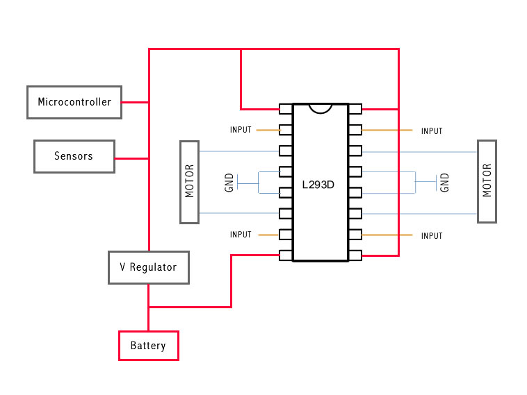
This is the most basic implementation of the chip.
As you can see, a 5V Voltage Regulator is between the battery and pins 1, 9, 16.
Pin 8 gets power before the VReg, if your motor needs for example 6V you should put
6V directly in this pin, all the other pins should not get more than 5V.
This will work with no problem at all, but if you want to do the right implementation
take a look at the next example:
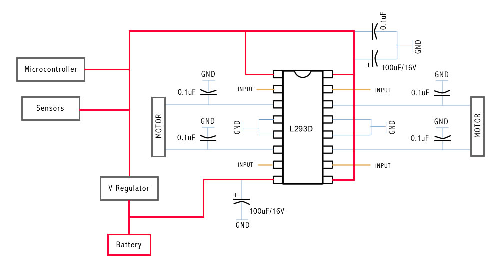
This is the correct Implementation (with the capacitors), and note that pin 8 is feeded
by unregulated voltage. This means that if your motors need more than 5V, you should
power this pin with that amount of voltage, and the rest of the circuit with 5V
The capacitors stabilize the current.
The same circuit on a breadboard:
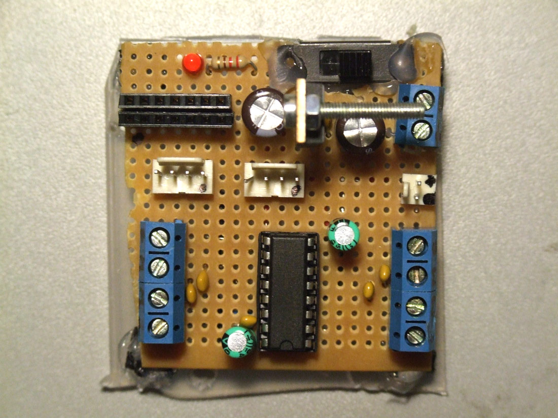
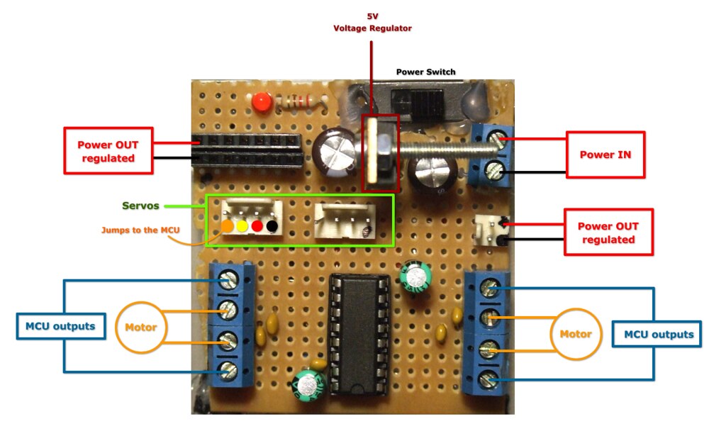
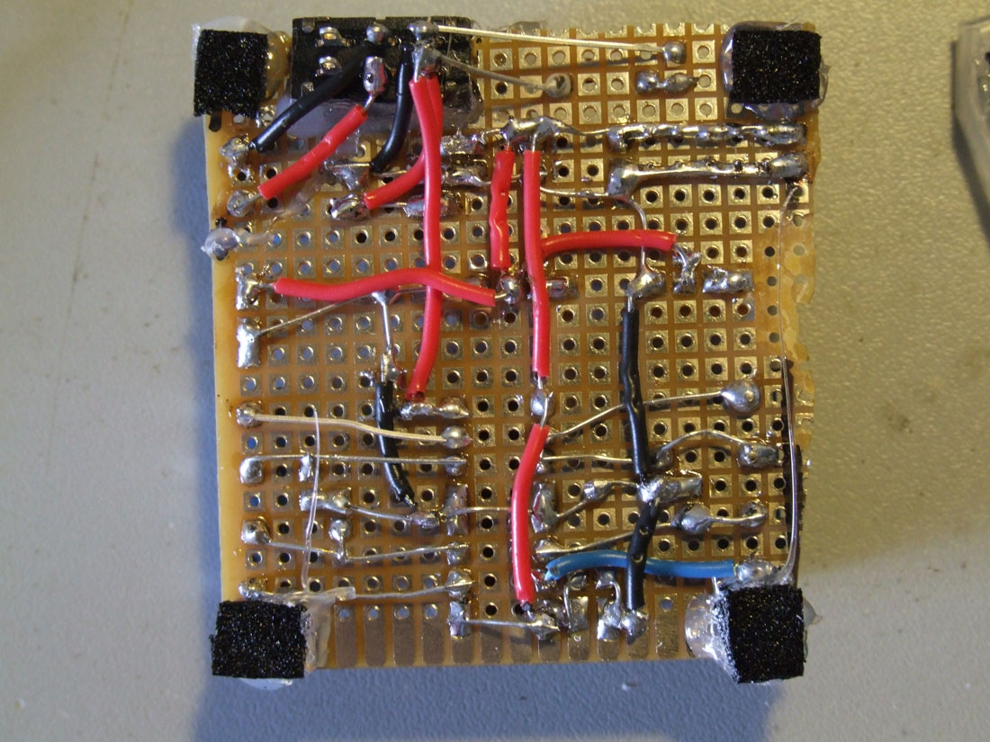
The same circuit on a breadboard: Soldered on a pcb and ready to go:
Servo motorları kullanmanın en sıkıntılı tarafı kontrol edilmesidir.
Servo motorlar herhangi bir dc motor gibi çalışmazlar. Verdiğiniz pals -sinyal
ile açısal olarak hareket ederler. Bu konumuzda programlama kullanmadan
bir servo motoru nasıl kontrol edebileceğimizi göreceğiz.
1. Adım:
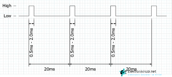
Servo motor seri sinyal gönderilerek kontrol edilir. Buna pwm- pulse with
modulation veya türkçesiyle sinyal genlik modülasyonu denir.
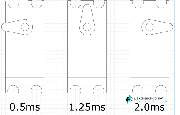
Servo motorun dönüş açısı verdiğiniz bu sinyalin uzunluğuna bağlıdır.
pwm sinyali Örneğin yukarıdaki şekilde sinyal her 20 ms de bir 0,5 ms ile 2 ms arasında uzunluklarda gönderilmiş. Eğer gönderilen sinyal 0.5 ms ise servo motor saat yönünün tersine, 2 ms ise saat yönüne dönecektir. (ms= milisaniye- saniyenin binde biri)
Sinyal üreten bir devre ile , sinyalin uzunluğunu potansiyometre kullanarak
0,5 ms ile 2 ms arasında ayarlamanız mümkündür. Bu bize servo motoru
istediğimiz gibi kullanma fırsatını verir.
2. Adım:
Sinyal üretmek için 555 timer devresini kullanacağız.
İki tip 555 timer devresi vardır: Astable , Monostable. Bu proje için astable devresini
kullanacağız. Bu devrenin beslemesi olduğu sürece sürekli sinyal üretileceği anlamına gelir.
555 timer devresinde zamanı kontrol etmek için dirençler ve kondansatörler kullanılıyor.
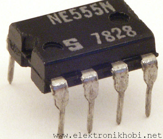
Devremizde NE555 entegresi kullanacağız.
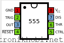
555 entegresi
555 astable devre şeması:
555 astable devresi
3. Adım:
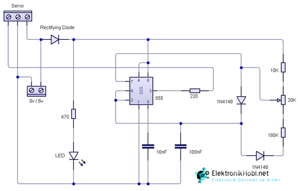
Aşağıdaki devre servo motor kontrol devresidir. İsterseniz Pcb üzerinde ,
isterseniz board üzerinde deneyebilirsiniz.
Önerimiz önce board üzerinde yapmanız. Bu şekilde plaket hazırlarken
malzemeleri daha iyi yerleştirebilirsiniz.
servo motor kontrol devresi
4. Adım:
Bitmiş haliyle devre aşağıdaki gibi olacak.
Entegreleri yuvalarıyla kullanmayı unutmayınız.
Kabloları deliklerden geçirerek kullanın. Bu şekilde çekmelere karşı daha
dayanıklı olacaktır.
servo motor kontrol devresi
555 astable devresi
pwm sinyali
Notlar:
Entegre yerleşimi için bakınız: Entegreler hakkında bilgiler