After long research and trial and error, I´ve came up to a new walkthrough regarding
this nice chip, the L293D.

Each project is one project and each one has its own unique power configurations,
so you must be aware of the best battery choice and how to distribute voltage through
your robot.
I strongly advice you to read the following articles:
Picking Batteries for your Robot
Once you’ve decided on batteries, how do you regulate the voltage
L293D gives you the possibility to control two motors in both directions – datasheet
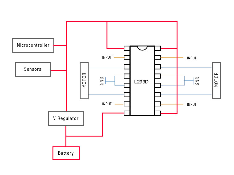
The L293D Circuit:
Basic Implementation:
This is the most basic implementation of the chip.
As you can see, a 5V Voltage Regulator is between the battery and pins 1, 9, 16.
Pin 8 gets power before the VReg, if your motor needs for example 6V you should put
6V directly in this pin, all the other pins should not get more than 5V.
This will work with no problem at all, but if you want to do the right implementation
take a look at the next example:

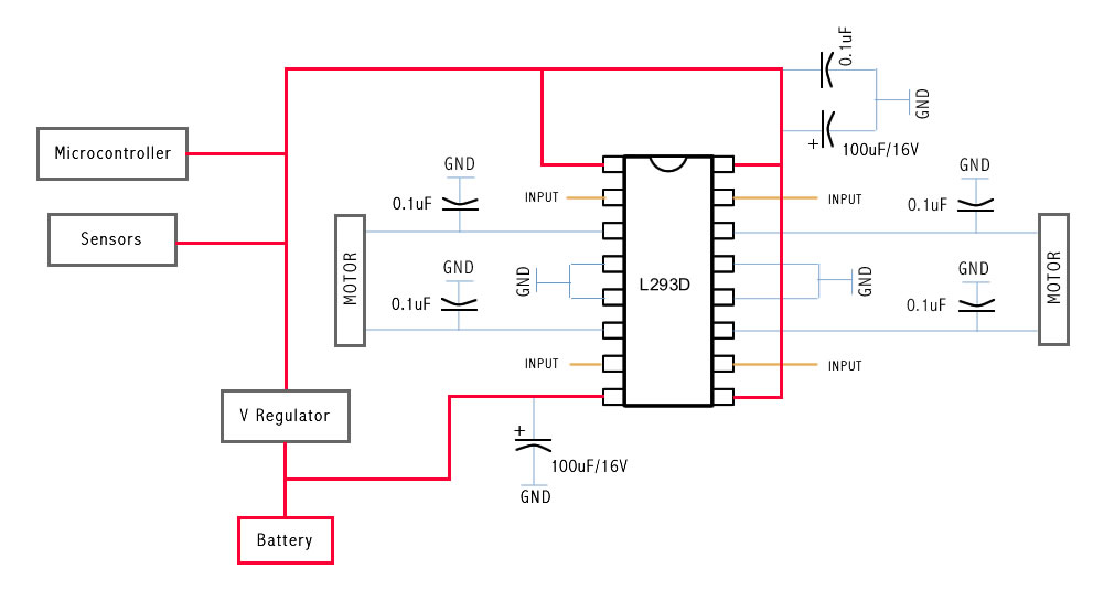
This is the correct Implementation (with the capacitors), and note that pin 8 is feeded
by unregulated voltage. This means that if your motors need more than 5V, you should
power this pin with that amount of voltage, and the rest of the circuit with 5V
The capacitors stabilize the current.

The same circuit on a breadboard:

The same circuit on a breadboard:
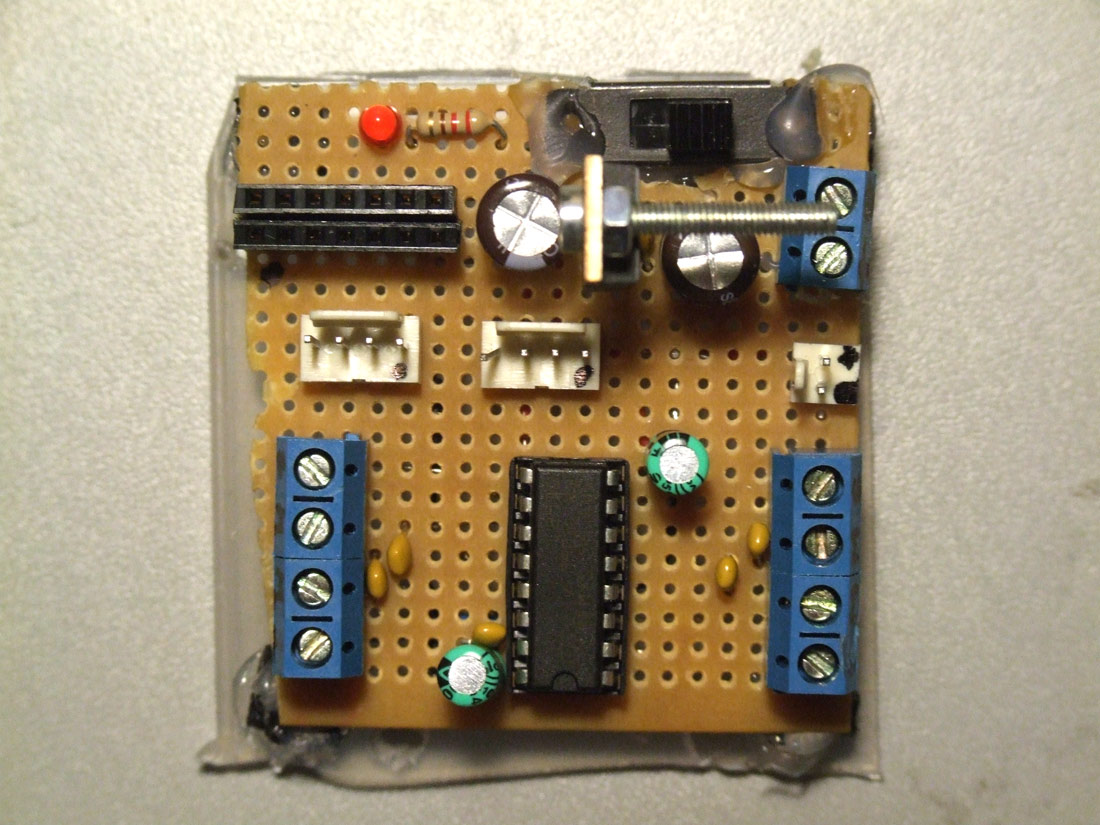
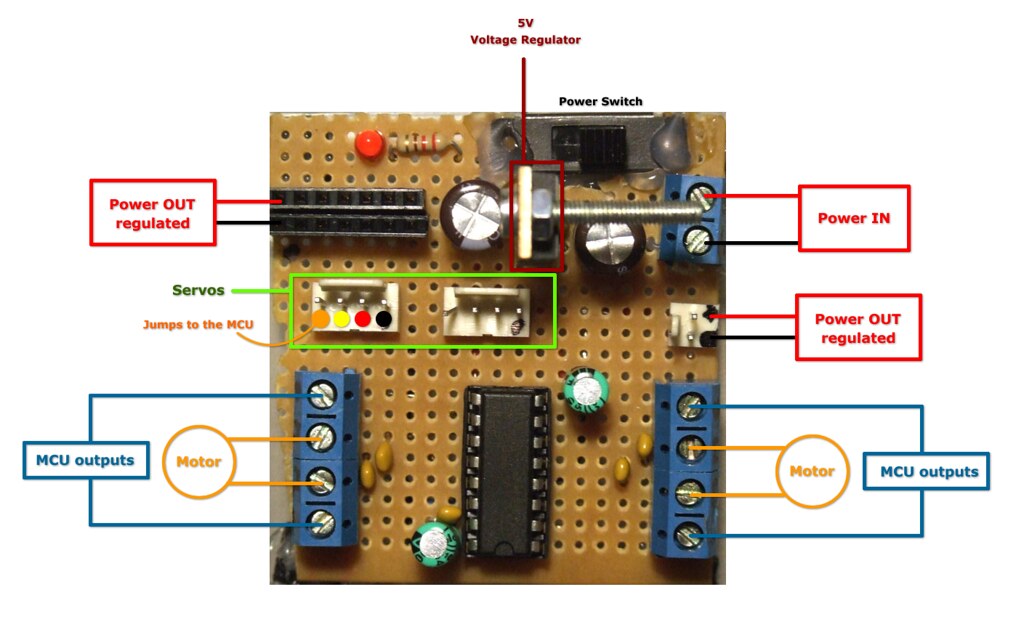
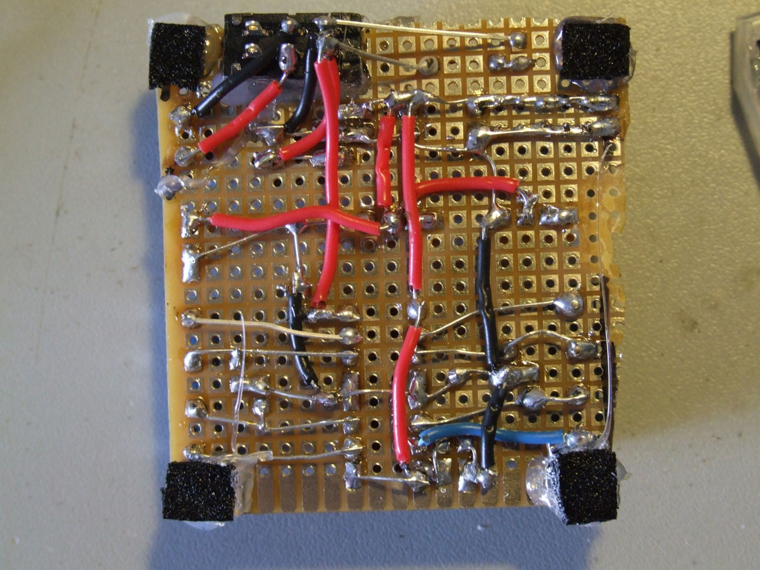
Soldered on a pcb and ready to go:


this nice chip, the L293D.
Each project is one project and each one has its own unique power configurations,
so you must be aware of the best battery choice and how to distribute voltage through
your robot.
I strongly advice you to read the following articles:
Picking Batteries for your Robot
Once you’ve decided on batteries, how do you regulate the voltage
L293D gives you the possibility to control two motors in both directions – datasheet
The L293D Circuit:
Basic Implementation:
This is the most basic implementation of the chip.
As you can see, a 5V Voltage Regulator is between the battery and pins 1, 9, 16.
Pin 8 gets power before the VReg, if your motor needs for example 6V you should put
6V directly in this pin, all the other pins should not get more than 5V.
This will work with no problem at all, but if you want to do the right implementation
take a look at the next example:
This is the correct Implementation (with the capacitors), and note that pin 8 is feeded
by unregulated voltage. This means that if your motors need more than 5V, you should
power this pin with that amount of voltage, and the rest of the circuit with 5V
The capacitors stabilize the current.
The same circuit on a breadboard:
The same circuit on a breadboard:
Soldered on a pcb and ready to go:


No comments:
Post a Comment