I found a website that solves all the wiring and coding issues; A library, written by Dean Reading.
I downloaded the zip file, copied it to /usr/share/arduino/libraries/ and unzipped it (includes the .cpp, the .h and an example sketch). (The directory is correct for my Linux Mint 16 system).
Given this library, the example code is simplicity itself.
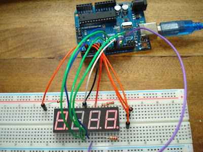
I used the wiring listed on the webpage, which when interpreted gives us :
Pin 1 is the LED top row, left pin
Pin 7 is the LED bottom row, left pin.
LED pin - Arduino pin
--------- -------------------
1 - 1K2 resistor to 2
2 - 6
3 - 11
4 - 1K2 resistor to 3
5 - 1K2 resistor to 4
6 - 7
7 - 10
8 - 9
9 - 13
10 - 8
11 - 12
12 - 1K2 resistor to 5
However, wired up and the sketch uploaded, all I got was swift random flickering from the display.
I was pretty sure it was wired as described, after several tries, so clearly my display had different pin inputs.
I looked at the code, the first obvious thing to change was the common cathode / anode option.
In the code, I replaced the line
sevseg.Begin(1,2,3,4,5,6,7,8,9,10,11,12,13);
with
sevseg.Begin(0,2,3,4,5,6,7,8,9,10,11,12,13);
And it worked perfectly. So my display has a common anode instead of cathode. No problem.
The next obvious point is that this method uses way too many arduino pins to use in any standalone project, which might also include a number of other sensors or motors so that you run out of arduino pins to use. One solution would be to use a separate arduino to drive this display, and pass the data through the serial port.
A nice solution that I found is to use shift registers. I have been using these quite a lot recently on my robot car. A separate Arduino Pro Mini can be bought for around £4 on EBay UK.
For a look at using shift registers, see this chap's webpage.
HIDDEN CODE
I downloaded the zip file, copied it to /usr/share/arduino/libraries/ and unzipped it (includes the .cpp, the .h and an example sketch). (The directory is correct for my Linux Mint 16 system).
Given this library, the example code is simplicity itself.
I used the wiring listed on the webpage, which when interpreted gives us :
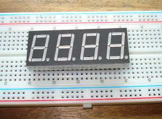
A 4 digit 7 segment LED display.
Pin 1 is the LED top row, left pin
Pin 7 is the LED bottom row, left pin.
LED pin - Arduino pin
--------- -------------------
1 - 1K2 resistor to 2
2 - 6
3 - 11
4 - 1K2 resistor to 3
5 - 1K2 resistor to 4
6 - 7
7 - 10
8 - 9
9 - 13
10 - 8
11 - 12
12 - 1K2 resistor to 5
However, wired up and the sketch uploaded, all I got was swift random flickering from the display.
Wired up, all I got was flickering.
I looked at the code, the first obvious thing to change was the common cathode / anode option.
In the code, I replaced the line
sevseg.Begin(1,2,3,4,5,6,7,8,9,10,11,12,13);
with
sevseg.Begin(0,2,3,4,5,6,7,8,9,10,11,12,13);
And it worked perfectly. So my display has a common anode instead of cathode. No problem.
Wired up the same, with the code changed to use a common anode - and it works beautifully.
A nice solution that I found is to use shift registers. I have been using these quite a lot recently on my robot car. A separate Arduino Pro Mini can be bought for around £4 on EBay UK.
For a look at using shift registers, see this chap's webpage.
HIDDEN CODE
https://kulogluelektronik.blogspot.com


No comments:
Post a Comment