

Downloads
Download the AVRStudio assembly source for the program: M8DPM091109A.asm
Download the AVRStudio hex file: M8DPM091109A.hex
Find updates at www.projects.cappels.org
Overview
- A 10 bit digital panel meter for positive voltage only.
- Input resistance: about 130k
- Ranges: 0 to 10.20 volts and 0 to 102.3 volts.
- Over range indication.
This project came from friend named Don's need for a digital panel meter for a
power supply project. This was further complicated by Don and me being on
different continents, and the problems that go with troubleshooting remotely.
Don had considered an ATMEGA8 project that was posted on the web, but
when contacted, the author was not helpful and seemed very discouraging.
So rather than pick through his code, trying to figure out what he had done,
I thought about writing the code myself. Most of it could be taken from other projects.
Then I realized that with only the 10 bit A-to-D converter on the available
AVR controllers, the resolution would only be 100 millivolts because
Don intended his power supply to supply over 20 volts.
The 10 bit A-to-D converter has a range of 0 to 1023. To explain in a little more detail,
using the ATMEGA8's internal 2.5 volt band gap reference means that by using a
resistive divider ahead of the A-to-D converter, the input could be scaled such that
any voltage range from 0 to 2.5 volts or higher could be accommodated.
If the range had less than 1024 steps, then some resolution would be lost.
For Don's application, a 102.3 volt scale would be necessary.
The least significant digit would be 100 millivolts.
And when he used the meter to measure (for example)
10.0 volts, the 100 millivolt resolution would be a little bit coarse.
"Ok, no problem", I thought. "He can have two ranges on the meter.
He can switch between two resistive dividers on the input to get a
10.23 volt full scale range and a 102.3 volt full scale range.

And why not have the meter switch between the two ranges automatically.
That would make the project a lot more interesting. I had always taken it
for granted that auto ranging voltmeters were pretty simple, and this
would be a chance to do something unusually analog with an AVR controller, so why not?
The Circuit


Find updates at www.projects.cappels.org
The circuit came out to be very simple and compact. The ATMEGA8 is the lowest pin count
AVR controller that I could find that has an onboard 10 bit A-to-D converter. It had no problem directly driving the four digits delivering an average approximately 50 milliamps to the display.
The on-chip clock oscillator also saved some parts. I am not sure whether the 8 uH inductor
and 0.33 uF decoupling capacitor on the analog VCC was necessary, but I used them as a good practice. Better to put a couple of extra parts on the board than to take the chance of
having to take the board back and add them later.
The schematic above shows an ISP (In Circuit Programming) connector, which I had
originally built onto the board so I could debug the firmware, using the crash-and-burn
method - write the code and see if it runs. After I was satisfied with the performance
of the meter, I cut off the portion of the board that had the ISP connector on it.
Power for the chip is regulated with a 7805 regulator. In this particular case, I used a TO-92 LM78L05 regulator. Measuring the current into the 5 volt input, I find a maximum of about 56 milliamps current drain, when displaying 08.88 volts. When powered from a 9 volt power source, the dissipation of the LM78L05 will be 224 mW. With a 200 degrees C per watt thermal resistance, junction temperature should be about 45 degrees above ambient. A little more calculation showed that the maximum safe input voltage to the LM78L05 is just a little above 12 volts if my maximum ambient temperature is 40 degrees C. In Don's case, where he would power the meter from 30 volts, it would be best to use a TO-220 version of the LM7805.


The input voltage divider is straight-forward. In the case of a 0 to 10.20 volt input range,
the resitive divider must reduce 10.20 volts to 2.50 volts (a reduction of about 4:1),
which is exactly what the circuit above was designed to do. The values of the
components were selected with two criteria in mind:
1) The A-to-D converter on the ATMEGA8 is optimized to operate when connected to a
10K impedance, so I didn't want to stray too far from that, and
2) The circuit should be stable, using parts on hand.
With the 10k pot midrange and the input shorted to ground, the A-to-D converter will see
32k Ohms on in parallel with 0.1 uf its input. Not the ideal 10k, but I thought that given
the low leakage current on the converter's input, this was a prudent tradeoff so I could
make the input resistor, R1, 127 k, limiting the input current to 1 milliamp when
connected to a 100 volt source. And besides, in the higher voltage scales,
with the 127k input resistor, the input resistance is about 4 k Ohms, a good trade-off again.


When in the 102.3 volt range, some additional resistors, R2, R3, and R4, are connected to
ground, so the input divider reduces 102.3 volts to 2.5 volts (40:1). These additional parts are switched in and out of the circuit by switching PORTB bit 0 I/O pin between being an input
with no pullup to a low output.
I have noticed that with some AVR controllers, one cannot switch the mode of the output pin
directly between these two states, so be sure to consult individual data sheets if you try
this on other controllers. Notably, on the ATTINY861, it took a little bit more
"bit twiddling" to switch an I/O pin between high impedance and low impedance states.
The 0.1 uf capacitor from the input of the A-to-D converter is there to not only keep
the impedance seen by the input from being too high, but also to act, in conjunction
with the input resistors, a low pass filter to reduce noise on the input.
The fixed resistors in the divider are 1%, 50 ppm/C metal film resistors that I bought
at a literal fire sale in Bangkok. I realize that not everybody has these exact values
on hand. But don't worry. Carbon film resistors should work about as well, though
you might see the calibration drift a little with temperature. Just pick carbon film
values that are close to the vales of the resistors shown in the schematic, and it should
work fine. You have the divider ratios, so if you feel the need, you can work out the
optimum component values.
If you only want one range, you can build the appropriate divider and leave the range
switch output, PORTB, bit 0, unused, and drive the appropriate decimal point through
a resistor on the ouput of an inverter, the input of which is connected to the cathode
of the digit whose decimal point you want illuminated.
The Firmware
After initialization, which includes setting up timer overflow interrupts, the controller
enters the main loop:
spin:
rjmp spin
So there the control sits in its infinite loop, waiting for interrupts.
Whenever an interrupt occurs, the controller is directed to one of five tasks, with names
such as "dodigit1" and" dodigit2", during which the four digits of the LED display are
scanned. A fifth task time is reserved for taking a set of measurements. During that time,
all digits are off, meaning that the digits are driven with a 20% duty cycle.
A set of measurements consists of taking eight successive measurements and dividing the
result by 8 by shifting the result right three times. I don't know if this really reduces the
noise that sometimes causes the least significant digit to flicker, but there was enough
time and code space to take all 8 measurements, and it might help in some installations.
When the input voltage measures over 1020 counts, corresponding to 10.20 volts,
PORTB, bit 0 is made into an low resistance connection to ground, switching the
meter to the 102.3 volt scale. If the input voltage exceeds 102.3 volts the display shows
"0FLo" to indicate the voltage is beyond the measuring range of the instrument.
When the input drops below 10.0 volts, the scale is switched back the 10.23 volt scale.
The difference between the thresholds to switch to the higher scale and that to switch to
the lower scale is 10.20 - 10.00 = 200 millivolts of hysteresis to assure that except in
cases in which the input voltage fluctuates wildly, the meter will not be constantly
switching its input range. The decimal points are changed to indicate the proper scale.
The conversion from a 16 bit unsigned number to a 4 digit decimal number is accomplished
with a very slow routine that I wrote a long time ago. The only thing to recommend this
routine is that it works and it doesn't use many registers.
If you have any questions about the source code, you are welcome to email me at the
address given at the bottom of this page.
Assembly tips
When you put this together, pay attention to the grounding. I suggest running a ground
connection directly from the ATMEAGA8 Analog Ground pin (Pin 22 on the DIP) to the
ground reference for the point you want to measure. If at all possible, avoid letting the
LED drive current return to the power supply through the same conductor. If you do,
make sure its a really low resistance connection, because the peak currents will be nearly 70 milliamps and the meters highest resolution is 10 millivolts. That works out to 140
milliohms for a 1 least-significant digit flicker due to led current induced ground loops.
Calibration
With no offset adjustment you will need to take what you get. The chips I tried allowed
me to get an output of "00.00" when I grounded the input.
There are two calibration pots, one for each input voltage range.
The 10.2 volt range needs to be calibrated first. Here is how I calibrated it:
Connecting the input of an operating meter to a power supply, I used my trusted Fluke
DVM to set the output voltage of the power supply to as close to 10 volts as I could, for
example, 9.99 volts, then I adjusted the 10k pot to obtain the same reading on the
digital panel meter.
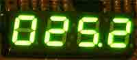
Then, I adjusted the power supply to its highest voltage setting, which was 25.2 volts
according to the Fluke, and then I adjusted the 47k pot to obtain a reading of 25.2 volts.
I think it would have been better to use a voltage close to 100 volts as the calibration voltage,
but 25.2 was the highest I could go that day.
Performance
I did not test the meter extensively, but I did exercise it a bit, and found that it tracked my
Fluke meter pretty well. Below is moving picture that shows the meter switching scales
as the power supply is adjusted.
Click on the photograph above to see the auto ranging in action.
The file is 800 kB


No comments:
Post a Comment