Showing posts with label Arduino. Show all posts

Thursday, 14 January 2021

Arduino Projeler (LCD 16X2, DH11) Dijital Termometre Nem Ölçer Yapımı 003


DHT22 veya DHT11 sıcaklık ve nem sensörü serisinin iki versiyonu var. Biraz benziyorlar ve aynı pinouta sahipler ama farklı özelliklere sahipler.


DHT22, açıkça daha iyi özelliklere sahip olan daha pahalı versiyondur. Sıcaklık ölçüm aralığı -40 ° C ile + 125 ° C arasında + -0.5 derece hassasiyetle, DHT11 sıcaklık aralığı +2 derece hassasiyetle 0 ° C ile 50 ° C arasındadır. Ayrıca DHT22 sensörü daha iyi nem ölçüm aralığına sahiptir, % 0 – 100 arasında% 2-5 doğrulukla, DHT11 nem aralığı ise% 5 ile% 20 doğrulukla ölçüm yapmaktadır.


Arduino DHT22 ve 16×2 Karakterli LCD Bağlantısı

Aşağıdaki çizim, 16 × 2 karakter LCD’deki sıcaklık ve bağıl nem değerlerini yazdıracaktır. Değerleri LCD’de görüntülememiz dışında aynı kodu kullanacağız


Arduino Projesi Olarak 16×2 LCD’li DHT11 ve DHT22

Sıcaklık ve nem seviyelerini izlemek istediğiniz bir fikriniz m var? Tam olarak doğru projeyi okuyorsunuz. Bu örnekte, LCD’yi DHT11, DHT22 sensörüyle birlikte Arduino’ya bağlayacağız.


indirme kod


PROJE VİDEOSU


Thursday, 7 January 2021

DHT11 sıcaklık ve nem sensörlü TM1637 Termometre Yapımı

Thermometer example: TM1637 4-digit 7-segment

 display with DHT11 temperature and humidity sensor


 4-Digit 7-segment displays are great for displaying sensor readings like temperature, humidity, voltage or speed. In the following example, I will show you how you can display temperature readings on the TM1637 display.

We will be using the popular DHT11 temperature and humidity sensor.

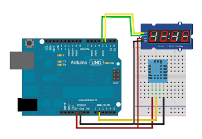
The wiring diagram below shows you how you can connect the DHT11 sensor in combination with the TM1637 display to the Arduino.

Note that the TM1637 display is connected in the same way as before.


Monday, 4 January 2021

Arduino 4-Digit & RTC module Clock

4-Digit Clock based on a RTC module

I have got a DS1302 Real Time Clock Module with Battery Backup, and I was eager

 to making a digital clock. As I also had a 7-segment 4-digit display, I was looking for the best way to make that clock. But I was always reluctant to use this type of display, because of the amount of wires it requires.

Then, "digital tube" 4-wire 4-digit display came across, and I knew that was the solution I was searching for. Now I had all the pieces of my little system.

Sunday, 15 March 2020

Arduino battery capacity tester

My first Arduino project was to build a battery capacity tester. I’ve got a box of rechargeable AA batteries, and it seams they’ve been less and less effective. Since most applications require 4 batteries, invariably one problem battery makes the rest of them look bad.

The Atmel ATMega328 microcontroller has 6 analog inputs with 10-bit A-to-D converters and a external AREF that allows you to define what voltage 0x3FF represents. In other words, it’ll give you ~1.4mV precision measuring 0-1.5V when given a 1.5V analog reference. Plenty accurate for a battery capacity measurement.

The principle is fairly simple. Apply a known load to a battery, record the voltage periodically while the battery discharges, stop recording at some point, and integrate to arrive at the area under the curve in order to derive the amp-hours delivered from the battery.

Enough theory, let’s see how it works. The UI starts with a helpful message:

Insert Battery

Saturday, 14 March 2020

Arduino Tabanlı Kalp Atışı Modülü

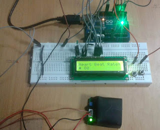
Kalp atış hızı , vücut ısısı ve kan basıncı izleme, insan vücudunun çok önemli parametreleridir. Doktorlar ateş veya vücut sıcaklığını kontrol etmek için termometre, kan basıncı ölçümü için BP monitörü ve kalp atış hızı ölçümü için nabız monitörü gibi çeşitli tıbbi cihazlar kullanır. Bu projede, bir dakika içinde kalp atışı sayısını sayan Arduino tabanlı bir kalp atışı monitörü inşa ettik . Burada , sensöre parmağınızı koyduğunuzda kalp atışını algılayan bir kalp atışı sensörü modülü kullandık.

Arduino and LCD- 0 Volt -- 1000 Volt

Abstract
The Arduino inbuilt 10 bit ADC, can be used for constructing / measuring the 0 Volt to 1000 Volt user selectable Digital Volt Meter. The 16x2 LCD display driver, connected with Arduino Uno will be used for displaying the measured voltage. This voltmeter can read only DC voltage.

ARDUINO 50V DIGITAL VOLTMETER USING MAX7219

M.Pugazhendi build a digital voltmeter using Arduino and MAX7219 display driver.

The Arduino inbuilt 10 bit ADC, can be used for constructing / measuring the 0Volt to 50Volt Digital Volt Meter. Popular MAX7219 display driver, connected with Arduino Uno will be used for displaying the measured voltage. This voltmeter can read only DC voltage.

Friday, 13 March 2020

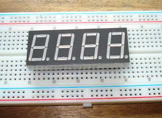
4 digit, 7 segment Display

I found a website that solves all the wiring and coding issues; A library, written by Dean Reading.
I downloaded the zip file, copied it to /usr/share/arduino/libraries/ and unzipped it (includes the .cpp, the .h and an example sketch). (The directory is correct for my Linux Mint 16 system).

Given this library, the example code is simplicity itself.
I used the wiring listed on the webpage, which when interpreted gives us :

A 4 digit 7 segment LED display.


Ultrasonic distance sensor

This was a great buy, easy to wire up and surprisingly accurate, when I measured up to 3 metres.
I found another blogger who had created the code.
The ultrasonic distance sensor and pin layout.


Arduino - PIR MOTION ALARM

Hello world! Today i made a simple and very cheap to build alarm System with a keypad, pir sensor, relay and a very loud alarm strobe. You have 30 seconds time to leave the room after activating the alarm system, of course this can be changed in the code to less or more seconds. Now it has been set to 30000 milliseconds.
You can change it at this line in the code:
const int timeDelay = 30000; //give yourself time to leave the room

Follow the next step for the Schematic, Code & Parts list.

Tuesday, 10 March 2020

Bootload the Arduino Mini

What is a bootloader, and what is bootloading?

The bootloader is the little program that runs when you turn the Arduino on, or press the reset button. Its main function is to wait for the Arduino software on your computer to send it a new program for the Arduino, which it then writes to the memory on the Arduino. This is important, because normally you need a special device to program the Arduino. The bootloader is what enables you to program the Arduino using just the USB cable.


When we refer to "bootloading" the Arduino, we are talking about using a special device (called an In-System Programmer or ISP) to replace the bootloader software.

Arduino Single-Sided Serial Board


If you don't have an easy way to order an Arduino board or kit, you can etch this PCB design by hand and solder it together. It is pin-compatible with the Arduino Diecimila, and should work with any Arduino shield.

This is the third revision of the board: the Arduino Single-Sided Serial version 3, or s3v3, or Arduino Severino. It was designed by Adilson Akashi, based on the previous version.

Monday, 9 March 2020

Board with WIFI Websocket Camera Demo

It is good news to hear that the Arduino IDE support was announced on the ESP8266 community forum, the source code can be found from . It is more than another Arduino board, but can be thought as an Arduino combined with a WIFI shield. With faster CPU speed and much smaller form of factor, most important the less than $10USD price is more attractive, you are worth to try although there are also some limitations. Setup is fairly simple with downloads for Linux, OS X, and Windows. A more detailed setup can be found from the adafruit guide.


Alarm Clock with Arduino

ABOUT THIS PROJECT

After designing the "Clock Set Date Time" and hearing the suggestion of ArduPic, I thought it would be a good idea and also useful, add a "wake-up alarm." A small change to the code and adding a few components: Here's "the Alarm Clock".

Compared to the previous project, I added a buzzer Piezzo, a diode LED, a resistor of 220 ohms, a button and as said before, I listened to the suggestion of "ArduPic" and I removed the resistance to "pull down."


Saturday, 7 March 2020

DS18B20 Thermometer using Arduino & 4 Digits 7 Segment Display


In this project we will learn how to design DS18B20 Based Thermometer using Arduino & 4 Digits 7 Segment Display. Simply we will interface Arduino with DS18B20 Digital Waterproof Temperature Sensor and display the temperature values in degree celsius on Common Cathode Display.


Live Weather Station using Arduino, RTC, Pressure & Temperature Sensor

Introduction:
A simple minor project as Live Weather Station using Arduino , RTC, Pressure & Temperature Sensor can be implemented easily. For example for viewing temperature we use thermometer and we don’t have any device to measure pressure, so we merely depend upon news. So here in this project we are going to develop a device that is capable of measuring temperature and pressure as well and after measuring it can be easily displayed in LCD with real time.


Voltmeter using Arduino & Seven Segement Display 0-50V DC

Introduction:
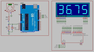
We are back again here with the latest Arduino Project, i.e DC Voltmeter using Arduino and Seven Segment Display. This time we will be interfacing Arduino with 7 segment display and MA7219 IC to measure voltage ranging from 0-50V with almost no error at all. This DC voltmeter is linear with voltage and shows a linear characteristics from 0.01 Volt to 50 Volt. Voltage beyond 50 Volt isn’t measurable by it. The above figure shows the 0-50V DC Voltmeter using Arduino and Seven Segment Display.


Thursday, 5 March 2020

Arduino based Digital Ammeter


Ammeter is used to measure current flow through any load or device. Here in this Arduino Ammeter, we will explain about measuring of current by using ohm’s law. It will be quite interesting as well as a good application of basic science that we studied in our school days.

All of us are well known of ohm’s law, It states that “the potential difference between two poles or terminals of an conductor is directly proportional  to the amount of current pass
through the same conductor” for constant of proportionality we use resistance, so here it comes the equation of ohm’s law.

V = IR

V = voltage across the conductor in Volt (v).
I = current pass through the conductor in Ampere (A).
R = resistance constant of proportionality in Ohm (Ω).
In order to find the current pass through the device we just rearrange the equation as below, or we can calculate with ohm's law calculator.

I = V / R

So in order to find out the current, we need some data:

Voltage
Resistance
We are going to build a series resistance along with the device. As we need to find voltage drop across the device, for that we need voltage readings before and after the voltage drop, that is possible in the resistance because of no polarity.

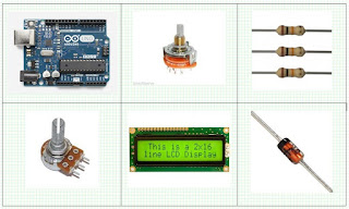
Required Components:

Arduino Uno.
Resistor 22Ω.
LCD 16x2.
LED.
10K pot.
Breadboard.
Multimeter.
Jumper cables.


Circuit Diagram and Connections:
The schematic diagram of the Arduino Ammeter Project is follows


The schematic diagram shows the connection of the Arduino Uno with LCD, resistor and LED. Arduino Uno is the power source of the all other components.

The Arduino has analog and digital pins. The sensor circuit is connected to the analog inputs from which we get value of the voltage. The LCD is connect with the digital pins (7,8,9,10,11,12).

The LCD has 16 pins the first two pins (VSS,VDD) and last two pins(Anode, Cathode) are connected to the gnd and 5v. The reset (RS) and enable (E) pins are connected to the Arduino digital pins 7 and 8. The data pins D4-D7 are connected to the digital pins of Arduino (9,10,11,12). The V0 pin is connected to the middle pin of pot. The red and black wires are 5v and gnd.


Arduino Code:
Complete code for arduino based ammeter to measure current, is given at the end of this article.


#include
LiquidCrystal lcd (7,8,9,10,11,12);

void setup() {
// put your setup code here, to run once:
Serial.begin(9600);
lcd.begin(16,2);
lcd.clear();
}

void loop() {
// put your main code here, to run repeatedly:
int voltage_value0 = analogRead(A0);
int voltage_value1 = analogRead(A1);

 int subraction_value =(voltage_value0 - voltage_value1) ;
 float temp_val = (subraction_value*0.00488);

 float current_value = (temp_val/22);
 Serial.print(current_value);
 lcd.setCursor(0,0);
 lcd.print("current value=");
 lcd.setCursor(0,1);
 lcd.print (current_value);
 lcd.print("A");
 delay(1000);
}


Wednesday, 4 March 2020

Complete Guide for Ultrasonic Sensor HC-SR04 with Arduino

Description

The HC-SR04 ultrasonic sensor uses sonar to determine distance to an object like bats do. It offers excellent non-contact range detection with high accuracy and stable readings in an easy-to-use package. It comes complete with ultrasonic transmitter and receiver modules.


Tuesday, 3 March 2020

"Arduino" Single-Sided Arduino Clone

I'm teaching "Electronics for Scientists" this semester, and I wanted to allow each student to have their own Arduino to play with for microcontroller lab exercises and possibly use for their final projects. The Arduino is not very expensive at roughly $30 per, but they add up quickly when you have a whole class of students needing one each. I'd been buying enough electronics equipment over the course of the semester that my department chair was showing an involuntary tic any time I knocked on his office door... So I built my own. They are a stripped-down variant of the Duemilanove.

Hoo-ah:
  • Standard Arduino form-factor and mount-points.
  • Accepts standard Arduino shields.
  • Single-sided board, easy to make with toner-transfer method. 
  • 16MHz ATmega328.
  • No SMT parts.
  • On-board 5V regulation.
  • Screw-terminal power-in connector, rather than barrel jack.
  • Pin-13 LED.
Meh:
  • Lacks on-board USB-Serial conversion, so programming requires an FTDI cable.
  • No 3.3V regulator.
  • This is as detailed a board as I ever want to make using toner-transfer.  
  • No TX/RX LEDs.
  • No ISP connector.
  • Three component-side jumpers. Couldn't quite get all traces on the back side!
None of these down-sides are significant for this application. The requirement of FTDI cable is inconvenient, sometimes, but I have 3-4 of them in the lab and students share them without too much squabbling.

My grader, Lena, did most of the drilling and soldering work. She's graduating next week, and I'll miss her, but the graduate program in Nuclear Engineering at University of New Mexico is going to be thrilled.

If you want to make your own single-sided Arduino variant, and this set of pros/cons is acceptable to you, here are the EAGLE files. One of the smart-asses in the electronics class immediately dubbed it the "Ayrduino"...

Note: the Arduino design, on which this is based, is licensed under the Creative Commons Attribution-ShareAlike 2.5 license; so this is available under that same license as well.

Parts list:
  • ATmega328P-PU (1)
  • 16MHz crystal (1)
  • 22 pF cap, ceramic (2)
  • Button, momentary tactile switch (1)
  • Angled header, 6-pin male (1) 
  • 0.1µF cap, ceramic (5)
  • Red LED (1)
  • Green LED (1)
  • 1N4001 diode (1)
  • 2-position screw terminal (1)
  • 7805 regulator (1)
  • 10kΩ resistor (1)
  • 510Ω resistor (2)
  • 47µF Al. Elect. cap (2) (short ones to fit under shield boards)
  • Female headers, 8-pin (2) (optional)
  • Female headers, 6-pin (2) (optional)
  • 28-pin IC socket (1) OR 14-pin IC socket (2) (optional)
  • Three short jumper wires
  • Single-sided PC board, 0.032" 1/2oz Cu.