 Presented FM transmitter bug is built using BF414 / BF324 / BF606 transistor. The 30cm antenna has a range of about 30m in the building, more in the open field. Power supply 2x AAA batteries have been used with voltage of 2.75 V. I added resistor 10K in parallel with 1.5pF capacitor so that the system works well when connected to an external source (mp3 player / computer). On the computer I had to reduce sound to about 35% of capacity, so that I do not have clipping. I managed to improve transmitter stability with simple shielding. The coil is 5 turns of enameled copper wire wound on 1 mm � = 5 mm.
Included on pages dedicated electronics simple micro transmitter bug. It's more than a wireless transmitter microphone bug, would be good to amplify the signal from the microphone to be heard and distant call. The transmitter operates in the CCIR FM (87-108 MHz), to re-tune to another frequency it would probably not be a problem.
First FM wireless transmitter microphone
Tab. First Tried types of transistors Table 1 Tested transistors
Type C2 C3
C e b BF606 excellent / best 33 pF 47 pF
C b e BF324 excellent / best 33 pF 47 pF
e b C 2N3906 good / good 27 pF 33 pF
e C b 2SA854 good / good 22 pF 27 pF
C b e BC307, BC558 bad / poor
low fT / low fT
Description of involvement
Involvement of wireless transmitter microphone is on Figure 1 . Signal from the electret microphone is modulated oscillator with T1. Microphone at the same time provides the oscillator DC bias. Voltage characteristics microphone MCE100 (GM electronic) on Figure 2 . It shows that from a voltage of about 1 V, the current flowing microphone little changed. This is used to stabilize the operating point of the oscillator. The oscillator I have tried several different transistors. For reliable operation it is necessary that the cutoff frequency of the transistor is at least 200 MHz, preferably 300 to 500 MHz.
Fig. Second VA characteristic electret microphone MCE100 Fig Second MCE100 electret microphone VA characteristic
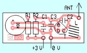
The preamplifier is built on the board according to Figure 3 , the layout of components on Fig 4. Coil the prototype had 6 turns enameled wire with a diameter of 0.8 mm, self-supporting wound on a mandrel (I used a drill bit shank) with a diameter of 5 mm. Need wire 11.5 cm. The listed components is an oscillator tuned to the lower end of the range, about 90 MHz. To the upper end of band reels only 5 loops. Oscillator tune stretching and compressing coil turns.
Another type of microphone can browse through more or less current. Measure the voltage because the R1. Resistor R1 decrease, if voltage on it exceeds 1.5 V. If the measured voltage is less than 1, it is necessary to increase the resistance of the resistor R1.
The transmitter is designed for power supply voltage of 3 V. The current consumption is about 3 mA. You can also use 2 or 3 NiCd - 2.4 or 3.6 V. When powered from the AC power in the broadcast signal appeared hum. Sufficed for its suppression capacitor 10 uF connected to the power supply directly to the board. When battery power was a signal without hum.
Serves as an antenna 20 cm long piece of wire. If longer necessary to connect the antenna, it will be necessary to separate the capacitor with the capacity of a few pF.
Note:
The involvement of bedbugs, I would recommend to add in parallel to the source of about 100 pF capacitor to ensure small internal source resistance at working frequency oscillator. This will improve performance and stability especially oscillator. I know from experience that some oscillators without this capacitor not run at all.
Transmitter components
R1 4.7 kOhm
R2 330 Ohm
C1 1.5 nF ceramic.
C2 33 pF, ceramic.
C3 47 pF, ceramic.
T1 BF324
Mic Electret microphone
L 6 z Cul diameter 0.8 mm self-supporting wound on a mandrel 5 mm 6 turns on 5 mm diameter. 11.5 cm length wire 0.8 mm diam.
PCB bcs10


No comments:
Post a Comment